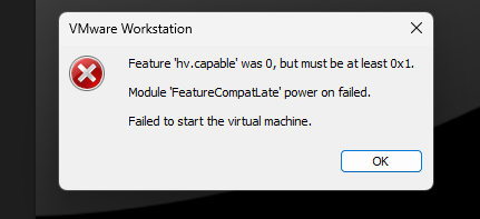
I have spent many days setting up my GNS3 LAB on my high spec laptop, only to be disappointed at the end of all that effort suddenly with a startup error “Feature ‘hv.capable’ was 0, but must be at least 0x1. Module ‘FeatureCompatLate’ power on failed. Failed to sart the virtual machine”
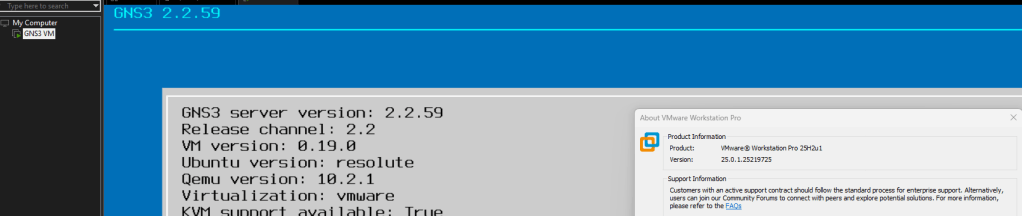
I have the GNS3 VM version 2.2.59 running on VMware Workstation version 25H2u1 which was working during the setup.
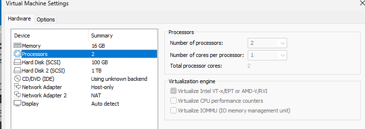
The GNS3 VM uses nested virtualization which requests the vCPU processor feature Virtualize Intel VT-x/EPT or AMD-V/RVI enabled for KVM to function in GNS3.
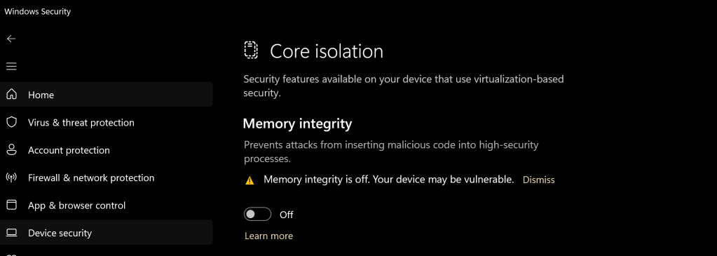
I started to investigate and research the error and it was identified that in Windows 11, the Core Isolation (Memory Integrity) feature in Windows Security –> Device Security was the cause of the error.
Resolution
In Windows Security -> Device security -> Core Isolation -> Disable Memory Integrity
Research
I did some digging to find out the root cause of the memory integrity causing error in the VMware workstation. I found out that the memory integrity is using hardware-based virtualization security which forces the CPU to grant exclusive access to the virtualization technology features to Windows restricting this features to other virtualization platform.
This article will be showing how to configure a Generic Encapsulation Tunnel also known as GRE Tunnel over IPSec.
disclaimer: note that this is a lab exercise only to show the configuration steps stated and may require additional modification based on your network environment.
The following network topology will be used to demonstrate this exercise.
Network Topology
The initial basic router configuration are below:
R1 configuration:
interface fastethernet 0/0 ip address 192.0.2.1 255.255.255.252 no shut ! int loopback 0 ip address 1.1.1.1 255.255.255.255 ! router ospf 1 network 0.0.0.0 0.0.0.0 area 0 ! R2 configuration:
interface fastethernet 0/0
ip address 192.0.2.2 255.255.255.252
no shut
!
interface fastethernet 0/1
ip address 203.0.113.1 255.255.255.252
no shut
!
int loopback 0
ip address 2.2.2.2 255.255.255.255
!
router ospf 1
network 0.0.0.0 0.0.0.0 area 0
!
R3 configuration:
interface fastethernet 0/1
ip address 198.51.100.1 255.255.255.252
no shut
!
interface fastethernet 0/0
ip address 203.0.113.2 255.255.255.252
no shut
!
int loopback 0
ip address 3.3.3.3 255.255.255.255
!
router ospf 1
network 0.0.0.0 0.0.0.0 area 0
!
R4 configuration:
interface fastethernet 0/0
ip address 198.51.100.2 255.255.255.252
no shut
!
int loopback 0
ip address 4.4.4.4 255.255.255.255
!
router ospf 1
network 0.0.0.0 0.0.0.0 area 0
!
Before going into the task, there are some information that is important to know why IPSec is with a GRE Tunnel:
GRE Tunnel
It is used to encapsulated the packets over a network between two network devices.
it does not provide encryption which makes it unsecure
IPSec
It is secure by providing encryption
it only supports uni-cast traffic which presents a problem for routing protocols that uses multicast to function.
What are the use cases for this technology?
Combining both technology makes it a suitable solution to create a secure connections over public or unsecured networks between two networks.
Lab Exercise
Once the routers has been configured accordingly using the initial base configuration, it is time to start the exercise.
In this exercise, two task are going to be done:
Configure a GRE Tunnel between R1 and R4
Configure a IPSec tunnel
Step 1 – Configure the GRE tunnel on R1and R4
Create a tunnel interface
R1(config)# interface tunnel 1
Assign an ip address to the tunnel interface
R1(config-if)# ip address 192.168.0.1 255.255.255.252
Set the source interface from where the tunnel will be connected
R1(config-if)# tunnel source fastethernet 0/0
Set the destination address of the router at the other end of the tunnel
Note: repeat the same steps on router R4 but replacing the respective source interface and destination address. It is important to note that the tunnel # is locally significant.
you can check the status of the tunnel after step 1 by running the show command as follows: