CCNP Encore: Configuring GRE Tunnel over IPSec

This article will be showing how to configure a Generic Encapsulation Tunnel also known as GRE Tunnel over IPSec.

disclaimer: note that this is a lab exercise only to show the configuration steps stated and may require additional modification based on your network environment.

The following network topology will be used to demonstrate this exercise.

Network Topology

The initial basic router configuration are below:

R1 configuration:

interface fastethernet 0/0
ip address 192.0.2.1 255.255.255.252
no shut
!
int loopback 0
ip address 1.1.1.1 255.255.255.255
!
router ospf 1
network 0.0.0.0 0.0.0.0 area 0
!
R2 configuration:

interface fastethernet 0/0

ip address 192.0.2.2 255.255.255.252

no shut

!

interface fastethernet 0/1

ip address 203.0.113.1 255.255.255.252

no shut

!

int loopback 0

ip address 2.2.2.2 255.255.255.255

!

router ospf 1

network 0.0.0.0 0.0.0.0 area 0

!

R3 configuration:

interface fastethernet 0/1

ip address 198.51.100.1 255.255.255.252

no shut

!

interface fastethernet 0/0

ip address 203.0.113.2 255.255.255.252

no shut

!

int loopback 0

ip address 3.3.3.3 255.255.255.255

!

router ospf 1

network 0.0.0.0 0.0.0.0 area 0

!

R4 configuration:

interface fastethernet 0/0

ip address 198.51.100.2 255.255.255.252

no shut

!

int loopback 0

ip address 4.4.4.4 255.255.255.255

!

router ospf 1

network 0.0.0.0 0.0.0.0 area 0

!

Before going into the task, there are some information that is important to know why IPSec is with a GRE Tunnel:

  • GRE Tunnel
    • It is used to encapsulated the packets over a network between two network devices.
    • it does not provide encryption which makes it unsecure
  • IPSec
    • It is secure by providing encryption
    • it only supports uni-cast traffic which presents a problem for routing protocols that uses multicast to function.

What are the use cases for this technology?

Combining both technology makes it a suitable solution to create a secure connections over public or unsecured networks between two networks.

Lab Exercise

Once the routers has been configured accordingly using the initial base configuration, it is time to start the exercise.

In this exercise, two task are going to be done:

  1. Configure a GRE Tunnel between R1 and R4
  2. Configure a IPSec tunnel

Step 1 – Configure the GRE tunnel on R1 and R4

  • Create a tunnel interface

R1(config)# interface tunnel 1

  • Assign an ip address to the tunnel interface

R1(config-if)# ip address 192.168.0.1 255.255.255.252

  • Set the source interface from where the tunnel will be connected

R1(config-if)# tunnel source fastethernet 0/0

  • Set the destination address of the router at the other end of the tunnel

R1(config-if)# tunnel destination 198.51.100.2 255.255.255.252

Note: repeat the same steps on router R4 but replacing the respective source interface and destination address. It is important to note that the tunnel # is locally significant.

you can check the status of the tunnel after step 1 by running the show command as follows:

R1(config)# do show ip interface brief

Step 2 – Configure a IPSec tunnel

  • Setup Phase 1 – set ISAKMP policy

R1(config)# crypto isakmp policy 14

  • Set encryption type

R1(config-isakmp)# encryption aes

  • Set authentication type

R1(config-isakmp)# authentication pre-share

R1(config-isakmp)# group 2

R1(config-isakmp)# exit

  • Set ISAKMP key and transform mode

R1(config)# crypto isakmp key 0 [keypass] address [192.51.100.2]

R1(config)# crypto ipsec transform-set [KWTRAIN] esp-aes esp-sha-hmac

R1(cfg-crypto-trans)# mode [transport|tunnel]

R1(cfg-crypto-trans)# exit

  • Configure an ACL for the traffic allowed to traverse the IPSec tunnel

R1(config)# ip access-list extended GRE-IN-IPSEC

R1(config-ext-nacl)# permit gre any any

R1(config-ext-nacl)# exit

  • Setup Phase 2 – linking ACL, transform set and peer ip to IPSec tunnel

R1(config)# crypto map VPN 10 ipsec-isakmp

R1(config-crypto-map)# match address GRE-IN-IPSEC

R1(config-crypto-map)# set transform-set KWTRAIN

R1(config-crypto-map)# set peer 198.51.100.2

R1(config-crypto-map)# exit

  • mapping interface to IPSec tunnel

R1(config)# interface f0/0

R1(config-if)# crypto map VPN

R1(config-if)# end

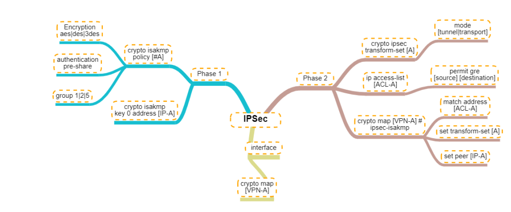
For person who are visual learners, here is a mind map of the configurations below.

Mindmap of the IPSec configuration commands

Fortinet: Publishing a Server access to the Internet via HTTP

This article is providing instructions on how to public a server/device to the internet using http. This article will go through the basic configuration.

After logging into to the Fortinet portal, got to Firewall Objects –> Virtual IP –> Virtual IP, select Create New

create_virtual_ip

There are number of parameters:

Name: Short description of services e.g. DVR HTTP-80

External Interface: this is the port connected to the internet link with the public IP address.

External IP Address/Range: this use only need if you have more that one IP address configured on the port. If not, you can leave the default 0.0.0.0

Mapped IP Address/Range: Enter the internal server IP address of device. e.g. our DVR 192.168.0.12

Port Forwarding: tick this option if you are using custom ports from the default e.g. external service port is 5000 from the outside connecting to (map to) port 80 on the internal server.

virtual_ip_info

Go to Policy –>Policy –> Create New

create_policy

Select the Source Interface/Zone to external port.

Select destination Address to the Virtual IP created earlier and select Service to HTTP since we are using port 80. If the service is not list add it with the custom ports. Select Enable NAT to allow external IP address to access the internal device through the fortinet.

policy_settings

Once save by clicking ok, it will be listed under the external port source port column in the Policy section.

policy_listed

Setting Up iSCSI in VMware ESXi 5.5

To begin this article, let me first discuss what is iSCSI and then the reason for requiring an iSCSI.

I love the definition of iSCSI provided by searchstorage.techtarget.com which stands for Internet Small Computer System Interface, that works on top of the Transport Control Protocol (TCP) and allows the SCSI command to be sent end-to-end over local-area networks (LANs), wide-area networks (WANs) or the Internet.

According to the same site, iSCSI works by transporting block-level data from an iSCSI initiator on a server and a iSCSI target on a storage device. The iSCSI protocol encapsulates SCSI commands and assembles the data in packets for the TCP/IP layer. Packets are sent over the network using a point-to-point connection.

The one of the main reason for using iSCSI connections is that it allows for the utilization of existing network resources such as NICs and network switches to present storage devices to servers once it has the iSCSI initiator software. this result in cost saving and it is is easily configured and it is available for both LAN, WAN and internet which mean easily access if it is relocated to the cloud

Now, let us go to the fun part…configuration of iSCSI in Vmware ESXi 5.5

It is important to note that there are two type of iSCSI initiator/target:

  1. Software
  2. Hardware

In this article, we are only going to go through the configuring of the Software iSCSI initiator from within the VMware Esxi 5.5 hypervisor.

Log into vSphere Web client

Select Host and Clusters

hostandcluster.png

Select the host you want you want to setup the the iSCSI Software adapter on.

Under the Host pane, select the Manage

Under Manage, Select Storage then Storage Adapters

ManageStorage_StorageAdapter

Select the Plus button

Storage-menu

Select Software iSCSI Adapter

software iscsi

Select OK to the following message

software-iscsi-msg-e1503502080853.png

Under Storage Adapters list, look for iSCSI Software Adapter and you will see the iSCSI Software Adapter listed.

software-iscsi-adapter.png

Highlight the adapter vmhbaXX (e.g. vmhba40) and under Adapter Detail, select Target –> Dynamic –> Add

AddDynamicTarget

Note: this allows you to add the primary IP address of the SAN or storage which allows the device LUNs to be discovered.

Enter the IP address of the target and leave the default port of 3260 for ISCSI communication. Then Select OK. For every iSCSI target, the IP address should be added.

SendTargetServer