Setting up a Cisco AP using the command line

This article is to document the CLI commands used to configure an Autonomous Cisco Access Point.

To configure the AP management IP address use the following command:

Interface BVI1

ip address [ip] [subnetmask]

no shutdown

Next, define the SSID properties including Name, Key method and password.

This particular configuration is using WPA2 to authenticate the users.

dot11 ssid [SSIDName]

authentication open
authentication key-management wpa version 2
guest-mode
wpa-psk ascii [password]

Next you will push this SSID on the 2.4 Ghz which is on interface dot1Radio 0 and if you want it to be available on 5 Ghz band as well, you will configure it on dot1Radio 1. The radio will be using the AES-CCM encryption mode.

interface dot1radio0

encryption mode ciphers aes-ccm

ssid [SSID-name]

no shutdown

Once you are done, you can save the configuration and test you wireless device.

Common Switch Commands for the HP FlexNetwork

I have recently had to interact with an HP FlexNetwork 5510 switches and the command syntax was totally different from the HP-Aruba 2530. This article is to document the common switch commands that I use on a daily basis.

  • Show (Display) the list of interfaces and their status

display interfaces brief

  • list the directly connected devices using LLDP

display lldp neighbor-information list

  • Enter enable mode or exec privilege mode

system-view

  • Save switch startup configuration

write

  • Show the running configuration

display current-configuration

  • Configure IP helper on an interface

interface [interface_type]

dhcp select relay

dhcp relay server-address [dhcp_ip_address]

  • Configure NTP Service

ntp-service enable
ntp-service unicast-server 10.71.152.229
ntp-service unicast-server 10.220.0.35

  • Configure SSH

ssh server enable

ssh client source interface [interface]

service-type ssh terminal

  • Configure the default gateway

ip route-static 0.0.0.0 [gateway_ipaddress]

  • Configure interface as layer 2

port link-mode bridge

  • Configure interface as layer 3

port link-mode route

  •  Configure the interface as a trunk

port link-type trunk

port trunk permit vlan [vlan-id]

  • Configure the local user account to manage the switch

local-user [username] class manage
password simple [password]
service-type [options: ssh telnet terminal]
authorization-attribute user-role [role-name]

I will be adding more command as time goes by and I get familiar with the CLI.

Cisco: Converting an Cisco AP 2600 from Lightweight AP to Autonomous mode

This article is about converting a Cisco AP version CAP2602E from a lightweight to Autonomous. (This can apply to other APs of similar models)

The tools that you will need to do the job:

  1. A TFTP server application…I am using Pumpkin (link here)
  2. Telnet tool…I am using Putty (link here)
  3. The Autonomous image for the Cisco AP (note: that the image file name will contain “k9w7“)
  4. Console cable
  5. Network cable
  6. Power adapter for the AP. (If you have a PoE switch to power the AP, then you can skip the adapter)

Now let us begin the process:

  1. Install the TFTP server application and start it up
  2. Install the PUTTY telnet tool
  3. Copy the image to the tftp folder path set in the TFTP server application. The image required for my Cisco AP CAP2602E is “ap3g2-k9w7-tar.153-3.JAB.tar”. Note when you get the image, it will need to be renamed from the image type “.tar” to “.default“. Example in my case, it will be ap3g2-k9w7-tar.default. Please ensure to follow this same syntax.
  4. Connect your AP directly to your computer.
  5. The static IP address of the computer on which your TFTP server software runs should be between 10.0.0.2 and 10.0.0.30.
  6.  Disconnect power from the access point.
  7. Press and hold MODE while you reconnect power to the access point.
  8. Hold the MODE button until the status LED turns red (approximately 20 to 30 seconds) and then release.
  9. The AP will start to broadcast to the tftp server for the image file. When the tftp server get a prompt from the AP, select Grant Access. (Note if the another image is requested, make a note of the image and try to get it.
  10. Once the image is correct, it will start to pull the image from the TFTP server and it takes about 10 minutes to load.
  11. Once the image has loaded, the AP will reboot.
  12. Then you can use the PUTTY to connect to the console and configure the AP as desired by assigning an IP address to the BVI interface. (default password Cisco/Cisco)
  13. Once the IP address is set, you can access it using the Web GUI.

I hope this article was helpful.


reference: https://community.cisco.com/t5/wireless-security-and-network/converting-the-air-lap1242ag-e-k9-from-lightweight-to-autonomous/td-p/632837


Securing the Web management for the HP 2530 switch

Whenever you get a HP/Aruba 2530 switch out of the box, it comes default with web management enabled using http. You can easily go to the IP address of the switch to view the switch details. To secure the web portal of the switch, do the following:

  1. Log into the switch
  2. Go into configuration mode
  3. Create a self-signed certificate for secure http access
    1. crypto pki enroll-self-signed certificate-name [SWITCHNAME] subject

    2. Enter each information requested
  4. To enable secure http, use command
    1. web-management ssl

  5. To disable http for web management, use command
    1. no web-management plaintext
  6. To added a login for the web portal, use the command:
    1. password manager user-name [loginname] plaintext [loginpassword]

I hope this was useful.

Fortinet: Publishing a Server access to the Internet via HTTP

This article is providing instructions on how to public a server/device to the internet using http. This article will go through the basic configuration.

After logging into to the Fortinet portal, got to Firewall Objects –> Virtual IP –> Virtual IP, select Create New

create_virtual_ip

There are number of parameters:

Name: Short description of services e.g. DVR HTTP-80

External Interface: this is the port connected to the internet link with the public IP address.

External IP Address/Range: this use only need if you have more that one IP address configured on the port. If not, you can leave the default 0.0.0.0

Mapped IP Address/Range: Enter the internal server IP address of device. e.g. our DVR 192.168.0.12

Port Forwarding: tick this option if you are using custom ports from the default e.g. external service port is 5000 from the outside connecting to (map to) port 80 on the internal server.

virtual_ip_info

Go to Policy –>Policy –> Create New

create_policy

Select the Source Interface/Zone to external port.

Select destination Address to the Virtual IP created earlier and select Service to HTTP since we are using port 80. If the service is not list add it with the custom ports. Select Enable NAT to allow external IP address to access the internal device through the fortinet.

policy_settings

Once save by clicking ok, it will be listed under the external port source port column in the Policy section.

policy_listed

Microsoft Powershell – Install and Configure AD Certificate Services (Windows Server 2016)

This article will demonstrate how to install and configure the Active Directory Certificate Services (AD CS) and the Certification Authority (CA) using both the Server Manager and corresponding Powershell cmdlet.

Using Powershell method

Check if the Active Directory Certificate Service is installed

Get-WindowsFeature AD-Certificate


To install the Certification Authority features, run the following cmdlet:

Install-WindowsFeature ADCS-Cert-Authority -IncludeManagementTools


Configuring the Active Directory Certificate Services with a Standalone Root CA on Host1.

Install-ADcsCertificationAuthority –Credential (Get-Credential) -CAType [StandaloneRootCA]CACommonName“domain-Host1-CA-1”CADistinguishedNameSuffix “DC=domain,DC=com” CryptoProviderName“RSA#Microsoft Software Key Storage Provider” -KeyLength 2048 HashAlgorithmName SHA1 ValidityPeriod Years ValidityPeriodUnits3DatabaseDirectory “C:\windows\system32\certLog”LogDirectory “c:\windows\system32\CertLog”Force

You can select the CA Type by setting the parameter for –CA Type to either StandaloneRootCA, StandaloneSubordinateCA, EnterpriseRootCA or EnterpriseSubordinateCA. For the CA options like the Cryptographic Provider, Hash Algorithm and Key length will have to be known so that it is selected correctly.

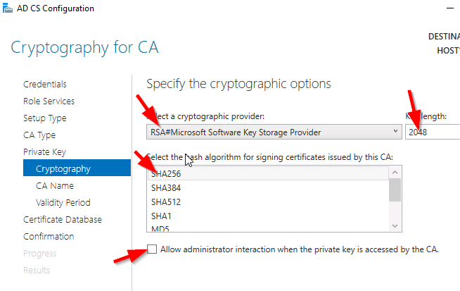
Example for the key length, the values can be 512, 1024, 2048, 4096 which has to be typed out.

For Hash Algorithm, the options are: SHA256, SHA384, SHA512, SHA1, MD5, MD4, MD2.

For the Cryptographic Provider, the parameter -CryptoProviderName can be:

  • RSA#Microsoft Software Key Storage Provider
  • ECDSA_P521#Microsoft Software Key Storage Provider
  • ECDSA_P256#Microsoft Software Key Storage Provider
  • ECDSA_P384#Microsoft Software Key Storage Provider
  • DSA#Microsoft Software Key Storage Provider

and any other…


Removing the AD CS and CA feature from the server.

Remove-WindowsFeature ADCS-Cert-Authority


Using the Server Manager


Go to Server Manager–> Manage –> Add Role and Features

servermgr

Select Role-based or feature-based installation

role-based

Select the Server to install it on

server

Tick the Active Directory Certificate Services

adcs_server_role

Tick the Certification Authority

CA_role

The feature will be installed and then you can select Configure Active Directory Certificate Services to setup the CA.

configure_ADCS_CA

Enter the Credential that have permission to configure the CA. Note the following:

For Standalone CA: you need local administrator rights

For Enterprise CA: you need Enterprise Admin rights

ca_credential

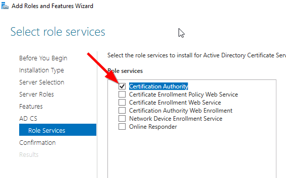
Select  role services: Certification Authority (CA)

configure_CA

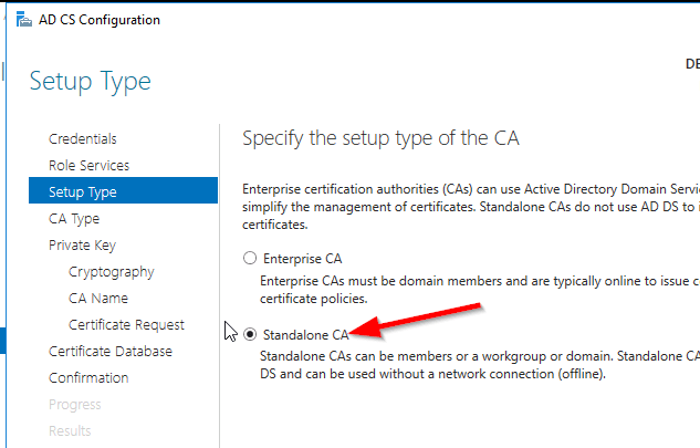
select Standalone CA. Once you know how to configure Standalone CA then you can easily configure Enterprise CA.

select_StandaloneCA

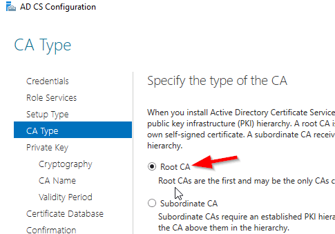
Select Root CA (this is the first CA)

select_RootCA

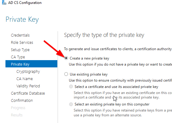
Select Create a new private key.

create_key

Select your preferred cryptographic provider, key length and hash algorithm

crypto_options

The Common Name and distinguished name suffix will be generated but you can enter your own name.

CA_CommonName

Select the validity period for the Certificate generated.

CA_Period

You can change certificate database and log path or let it remain at the default path

CA_DB-log

Confirm configuration settings of CA.

CA_result_page

Once the CA installation is complete, you can go to Server Manager –> Tools –> Certification Authority to view CA server in the MMC.


Cisco 2960 Error: %ILPOWER-3-CONTROLLER_PORT_ERR: Controller port error: Power Controller reports power supply VEE under voltage and lockout

I got a report that all our VoIP phone were down in a particular area that were connected to a Cisco 2960 switch. Upon investigation,

Initially, I ran the following show commands to check the status of the ports and power:

show power inline

The switch output:

showpowerinline

It was indicating that there was no device drawing power from the switch which was strange because there were VoIP phones connected to this switch.

With further checks, I came across these errors in the event logs:

poe_error

This error was telling me either the switch power module failed or some device caused a surge in power that causes the port power module to overload.

My resolution: Restart the switch which restored the switch to normal operations.

Being curious about the error, I researched it and came across this Cisco report:

https://quickview.cloudapps.cisco.com/quickview/bug/CSCsw18530

It was stating that this error is due to a bug in a particular version of IOS for 2960 switches.

The solution is:

Workaround:

Longer cable (>50ft) seems to fix the issue in most cases.

Solution

This issue is fixed in 12,2(55)SE3 , 12.2(58)SE1 and later releases. The
following interface configuration commands have to be applied to resolve the
issue,

Switch(config)# int x/y
Switch(config-if)# power inline port 2x-mode
Switch(config-if)# shut
Switch(config-if)# no shut

The fix is present in the following platforms :

3750-E,3560-E, 3750-X, 3560-X, 3560-C, 2960S, 2960,2960C,2960X

The other platforms do not support 2X power mode and the workaround would be to
use a longer cable.

Setup Cisco Router 1841 for NATing over two interface with Dynamic address.

I was given the challenge to setup a Cisco 1841 router with two Fast Ethernet interface and a four Fast Ethernet-port switch module to configure redundancy across two Internet Service Providers (ISP).

RouterRedunantLink

I know that to accomplish this task, I will need  to do the following:

  • Configure the interfaces to get DHCP IP address from the two ISPs
  • Configure NATing from the LAN to the two ISPs for internet access
  • Configure IP SLA or Tracking to detect when the primary link goes down
  • Configure DHCP for the LAN devices
  • Configure Switch Virtual Interface (SVI) as the gateway for the LAN
  • There are also other features included to make the configuration easier such as IP access-list and route-map to link the IP address to the ISP interface for the NATing process.

Configure IP SLA for detecting failure of primary ISP link:

ip sla monitor 1

type echo protocol ipIcmpEcho 8.8.8.8 source-interface f0/0

timeout 1000

threshold 1000

frequency 6

ip sla monitor schedule 1 life forever start-time now

track 10 rtr 1 reachability

delay up 10

The command track 10 rtr is similiar to track 10 ip sla in newer router IOS. If the rtr parameter is not listed then use ip sla. Also some router IOS may not have ip sla monitor, instead it only has ip sla with the monitor parameter.

Now to configure the ISP interfaces and set the primary link tracking:

interface Fa0/0

ip dhcp client route track 10

ip address dhcp

ip nat otside

no shutdown

description PrimaryLink

interface f0/1

ip address dhcp

ip nat outside

description BackupLink

no shutdown

Using the command ip dhcp client route track 10 helps to track the ISP network status using the IP SLA configured previously.

Creating the SVI for the LAN:

interface VLAN 1

ip address 192.168.10.1 255.255.255.0

ip nat inside

description LAN_GWY

Setting  up the DHCP scope for the LAN (IP range 192.168.10.100-150):

ip dhcp pool LAN10

network 192.168.10.0 /24

default-router 192.168.10.1

dns-server 8.8.8.8 4.2.2.2

ip dhcp excluded-address 192.168.10.1 192.168.10.99

ip dhcp excluded-address 192.168.10.151 192.168.10.254

Setup the switch module ports as access ports for the LAN:

interface range f1/0 – 3

switchport mode access

Configure NATing for Internet access:

Please note that from previously entered command for the interfaces and SVI, there is an command ip nat inside and ip nat outside telling NAT which direction are the IP address translated.

Setup Access list for LAN Subnet (192.168.10.0/24)

ip access-list standard LAN-Subnet

permit 192.168.10.0 0.0.0.255

Setup Route-map to match LAN subnet to the two ISP interface:

route-map NAT_TO_PrimaryLink

match ip address LAN-Subnet

match interface f0/0

route-map NAT_TO_BackupLink

match ip address LAN-Subnet

match interface f0/1

Using route-map allows for the same source subnet to be map to two interfaces for the NATing.

Setup NATing for each ISP link to LAN Subnet

ip nat inside route-map NAT_TO_PrimaryLink interface f0/0 overload

ip nat inside route-map NAT_TO_BackupLink interface f0/1 overload

Change the administrative distance for Primary link

ip route 0.0.0.0 0.0.0.0 f0/0 dhcp 10

ip route 0.0.0.0 0.0.0.0 f0/1 dhcp 20

The default route 0.0.0.0 are set to ensure that they are setup with the specified administrative distance 10 and 20 for Primary and Backup link respectively.


Microsoft: Manipulating Windows Network Adapter using PowerShell

This article is about configuring the network adapter using PowerShell cmdlet:

To get a list of the names of physical network adapter, the following command was used:

Get-NetAdapter -Physical

To get the IP address assigned to the network adapter:

Get-NetIPAddress | Format-Table

To enable/disable the network adapter:

Enable-NetAdapter [-Name] “NetAdapterName”

Disable-NetAdapter [-Name] “NetAdapterName”

Restart-NetAdapter [-Name] “NetAdapterName”

To set dynamic IP address assignment for network adapter:

Set-NetIPAddress -AddressFamily IPv4 -PrefixOrigin Dhcp

To set static IP address for network adapter:

New-NetIPAddress -InterfaceIndex [NetAdapterIndex] -IPAddress 192.168.0.1 -PrefixLength 24 -DefaultGateway 192.168.0.5

Set-NetIPAddress -InterfaceIndex [index] -IPAddress 10.0.0.9 -PrefixLength 24

To set DNS IP address for network adapter:

Set-DnsClientServerAddress -InterfaceIndex 12 -ServerAddresses(“10.0.0.1”,“10.0.0.2”)

Or

Set-DnsClientServerAddress -InterfaceIndex 12 -ResetServerAddresses

For more commands and help on this topic, you can visit the Microsoft documentation site here.

Manipulating Windows Network Adapter using Network Shell

This adventure of configuring the network adapter started when I required admin rights to modify the settings because UAC (User Access Control) was disabled which prevented the prompting of admin privilege. The challenge was that I did not want to log off or switch user account hence I had to resort to using elevated privilege for the command prompt and utilize the network shell.

To get a list of the names of network adapter, the following command was used:

netsh interface show interface

To get the IP address assigned to the network adapter:

netsh interface ipv4 show addresses

To enable/disable the network adapter:

netsh interface set interface name=”NameOfInterface” admin=[ENABLED/DISABLED]

To set dynamic IP address assignment for network adapter:

netsh interface ipv4 set address source=dhcp

To set static IP address for network adapter:

netsh interface ipv4 set address static 10.0.0.9 255.255.255.0 10.0.0.1

To set DNS IP address for network adapter:

netsh interface ipv4 set dnsservers source=dhcp

Or

netsh interface ipv4 set dnsservers static 10.0.0.10 primary

For WLAN network adapter:

netsh wlan show interfaces

Show the Wireless networks broadcasting:

netsh wlan show networks

Show the WLAN profiles on computer:

netsh wlan show profiles

Connect to one of the WLAN profile configured on computer:

netsh wlan connect name=[ProfileName]

Disconnect from the currently connected WLAN SSID

network wlan disconnect name=[InterfaceName]

For more commands and help on this topic, you can visit the Microsoft documentation site here.