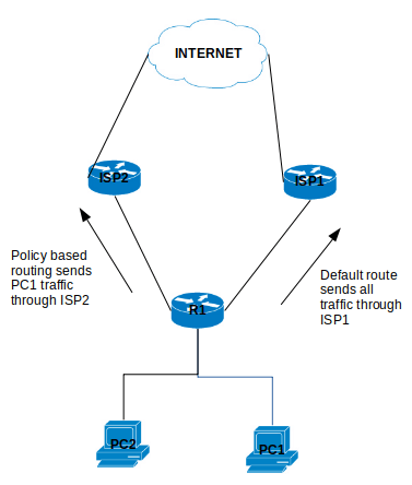
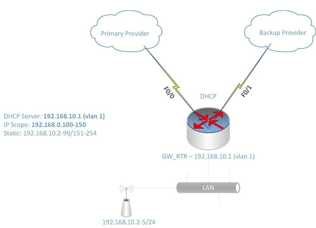
I was given the challenge to setup a Cisco 1841 router with two Fast Ethernet interface and a four Fast Ethernet-port switch module to configure redundancy across two Internet Service Providers (ISP).
I know that to accomplish this task, I will need to do the following:
- Configure the interfaces to get DHCP IP address from the two ISPs
- Configure NATing from the LAN to the two ISPs for internet access
- Configure IP SLA or Tracking to detect when the primary link goes down
- Configure DHCP for the LAN devices
- Configure Switch Virtual Interface (SVI) as the gateway for the LAN
- There are also other features included to make the configuration easier such as IP access-list and route-map to link the IP address to the ISP interface for the NATing process.
Configure IP SLA for detecting failure of primary ISP link:
ip sla monitor 1
type echo protocol ipIcmpEcho 8.8.8.8 source-interface f0/0
timeout 1000
threshold 1000
frequency 6
ip sla monitor schedule 1 life forever start-time now
track 10 rtr 1 reachability
delay up 10
The command track 10 rtr is similiar to track 10 ip sla in newer router IOS. If the rtr parameter is not listed then use ip sla. Also some router IOS may not have ip sla monitor, instead it only has ip sla with the monitor parameter.
Now to configure the ISP interfaces and set the primary link tracking:
interface Fa0/0
ip dhcp client route track 10
ip address dhcp
ip nat otside
no shutdown
description PrimaryLink
interface f0/1
ip address dhcp
ip nat outside
description BackupLink
no shutdown
Using the command ip dhcp client route track 10 helps to track the ISP network status using the IP SLA configured previously.
Creating the SVI for the LAN:
interface VLAN 1
ip address 192.168.10.1 255.255.255.0
ip nat inside
description LAN_GWY
Setting up the DHCP scope for the LAN (IP range 192.168.10.100-150):
ip dhcp pool LAN10
network 192.168.10.0 /24
default-router 192.168.10.1
dns-server 8.8.8.8 4.2.2.2
ip dhcp excluded-address 192.168.10.1 192.168.10.99
ip dhcp excluded-address 192.168.10.151 192.168.10.254
Setup the switch module ports as access ports for the LAN:
interface range f1/0 – 3
switchport mode access
Configure NATing for Internet access:
Please note that from previously entered command for the interfaces and SVI, there is an command ip nat inside and ip nat outside telling NAT which direction are the IP address translated.
Setup Access list for LAN Subnet (192.168.10.0/24)
ip access-list standard LAN-Subnet
permit 192.168.10.0 0.0.0.255
Setup Route-map to match LAN subnet to the two ISP interface:
route-map NAT_TO_PrimaryLink
match ip address LAN-Subnet
match interface f0/0
route-map NAT_TO_BackupLink
match ip address LAN-Subnet
match interface f0/1
Using route-map allows for the same source subnet to be map to two interfaces for the NATing.
Setup NATing for each ISP link to LAN Subnet
ip nat inside route-map NAT_TO_PrimaryLink interface f0/0 overload
ip nat inside route-map NAT_TO_BackupLink interface f0/1 overload
Change the administrative distance for Primary link
ip route 0.0.0.0 0.0.0.0 f0/0 dhcp 10
ip route 0.0.0.0 0.0.0.0 f0/1 dhcp 20
The default route 0.0.0.0 are set to ensure that they are setup with the specified administrative distance 10 and 20 for Primary and Backup link respectively.