
In general computing, storage is a very important component of a systems because it is where all the data is stored on a systems. With this reason, it is important that when moving workloads to the Cloud, storage is a critical part of the discussion.
In this article, the focus will be on storage redundancy options in the Azure and how it works.
There are four (4) basic storage redundancy options in Azure:
- Locally Redundant Storage (LRS)
- Zone-Redundant Storage (ZRS)
- Geo-Redundant Storage (GRS)
- Geo-Zone Redundant Storage (GZRS)
To better understand how the storage redundancy, a few terms will need to be defined:
Region – it is a large geographical area. For example California or Virigina (in Azure it is referred to as West US and East US respectively)
Availability Zones (AZ) – it is a logical set of one or more datacenters within a single region. The AZ shares the same network, power and cooling which is a single point of failure for the AZ. Every Region will have alteast 1 AZ and atmost 3 AZes.
Now, I am will be going over the storage redundancy.
Locally Redundant Storage (LRS)
Within one Availability Zone, there are muliple racks of servers with storage that will support the redundancy as required. The LRS takes advantage of these storage, by making 3 copies of the data across three (3) independent storage within a datacenter (Availability Zone).

The LRS protects against system level failures which includes server and disk within a datacenter.
Zone-Redundant Storage (ZRS)
The next level of storage redundancy is ZRS which has three (3) copies of your data across three(3) availability zones (data centers). This storage redundancy protects the data against datacenter level failures which is affected by network or power outage.

For the remaining storage redundancy, the replication to the secondary region is based on the primary region selected using the region pair. Additionally, the next redundancy will need to be activated for the service to be back online.
Geo-Redunant Storage (GRS)
This storage redundancy method utilizes the LRS as part of it functionality. The data is replicated across two regions where three (3) copies of the data is created within each region. This redundancy not only increase the data available against systems failures but also against regional outage affected by natural disasters namely earthquakes, floods or hurricanes.

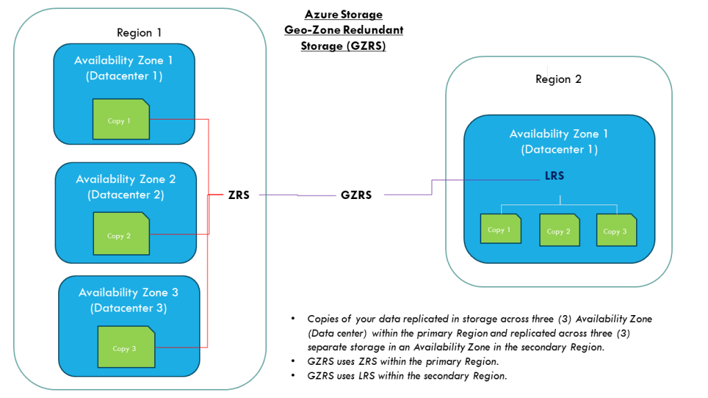
Geo-Zone Redundant Storage (GZRS)
This storage redundancy is similiar to the GZS except that the primary region use the ZRS instead of the LRS method. The benefits of redundancy GZRS verse GRS is that when there is a datacenter level failure in the primary region, the data will still be available and failover to the secondary region will not be necessary.
Limitations
Not all storage redundancy are available for all storage account type. An example is the Premium Azure Files which uses SSD-backed storage and only supports LRS and ZRS.
Conclusion
For each of the storage redundancy, selecting the right option will be based on business requirements and cost. It is important to assess the impact to the buiness and choose the option that balance cost and availability to keep the business operational.
Reference:
https://learn.microsoft.com/en-us/azure/storage/files/files-redundancy
